Explore how to use the Line tool with Polar Tracking switched on. When using any drawing command, Polar Tracking allows you to snap to specific angles with the cursor instead of typing the angles into the command line. This can make your drawing much faster and easier.
This exercise is excerpted from Noble Desktop’s past AutoCAD training materials and is compatible with Photoshop updates through 2020. To learn current skills in AutoCAD, check out AutoCAD Bootcamp and AutoCAD classes in NYC and live online.
Topics Covered in This AutoCAD Tutorial:
Using Polar Tracking with the Line Command
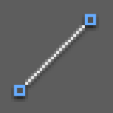
Exercise Preview
![]()
Exercise Overview
In this exercise, you’ll learn how to use the Line tool with Polar Tracking switched on. When using any drawing command, Polar Tracking allows you to snap to specific angles with the cursor instead of typing the angles into the command line. This can make your drawing much faster and easier!

Using Polar Tracking
- In AutoCAD, close any files you have open.
- From the Start tab, click on the large Start Drawing button to create a new drawing.
- In the bottom right Status bar, click on Polar Tracking
 to switch it on (so it’s blue).
 -
To the right of the Polar Tracking icon
click the arrow  and select the incremental angle 45,90,135,180 from the menu that opens.
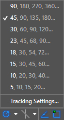
NOTE: Incremental angles are preset angles that can be divided evenly into a 360° circle. You can add additional custom tracking angles by clicking on Tracking Settings at the bottom of the menu.
- Click on the Line tool
 to start the Line Command.
 - Type in a first point of 0,0 and press Enter.
-
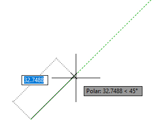
Move the cursor upwards and snap to the green vertical 90° Polar Tracking line. When you snap to a Polar angle, the distance and angle will appear in a gray box:
USE ACTUAL SCREENSHOT
-
Type in a distance of 10 and press Enter to complete the first line segment.
As you’ll continue to see throughout the exercises, using Polar Tracking to determine the angle means that you do not need to press the Tab key and enter the angle manually, which can save you a lot of time.
- For the next line segment, move the cursor up and to the right until it snaps to the 45° green Polar Tracking line.
- Type in a distance of 10 and press Enter to complete the second line segment.
- For the third line segment, move the mouse to the right to snap to the 0° horizontal angle, then enter a distance of 20 and press Enter.
- Move the cursor downwards for the next line segment, snap to 90° and enter a distance of 10.
- For the next line segment, snap to 135° and enter 10 for the distance.
To complete the last bottom horizontal line segment, click on the Close option in the command line.
Nice work! Save the file by going to File > Save As and navigating into Class Files > AutoCAD Class.
Name the file polar line drawing.dwg and click Save. Keep the file open as we’ll continue to work on it in the next exercise.