Explore this comprehensive AutoCAD tutorial that provides a deep dive into plotting and check plotting, covering everything from the basics of plotting a layout and understanding plot styles to check plotting from the model tab.
This exercise is excerpted from Noble Desktop’s past AutoCAD training materials and is compatible with Photoshop updates through 2020. To learn current skills in AutoCAD, check out AutoCAD Bootcamp and AutoCAD classes in NYC and live online.
Topics Covered in This AutoCAD Tutorial:
Plotting (Printing), Check Plotting
Exercise Preview
Exercise Overview
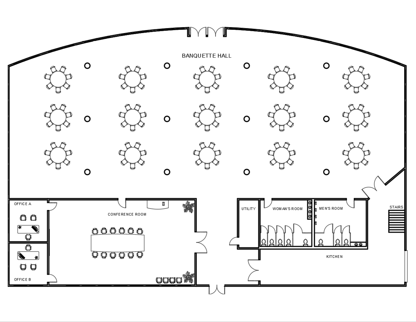
In this exercise, you will plot a layout. In AutoCAD, the term Plot is used instead of Print. Plotting can refer to printing on paper or fabrication with CNC machines.

Plotting (Printing)
You should still have Layouts-Banquet Hall.dwg open.
-
Now you will plot (print) a layout. Switch to the A-Sized Layout tab. Before you plot, you can check to see that your settings are correct with the Preview command. Select Preview from the File menu or type PREVIEW ENTER. The Plot Preview dialog box will appear displaying what the finished plot will look like so you can correct any errors.
The Plot Preview reveals two problems with this layout. One problem is the edge of the viewport is visible. Typically, Viewport layers or set to not plot, so the edges aren’t visible in the final print. If the viewport is visible in the Plot Preview, it’s usually because the viewport was placed on the wrong layer. You will check what layer the viewport is on after you close the Plot Preview.
The other problem is that the colors in the plot match the colors of the objects. All the objects in the plot should be black regardless of the layer colors. This problem usually arises because no Plot Style was assigned in the Page Setup. You will also check this after the Plot Preview is closed. Click the X in the circle at the top of the Plot Preview panel to close it.
NOTE: The colors of the plot are the same colors as the objects. All objects should be plotted in black.
Make sure you are in Paper Space and select the Viewport. The Layer Control will indicate that the viewport is on the A-Walls layer. Move the viewport to the Viewports layer. The Viewports layer is set to not plot in the Layer Properties Manager, so the edge of the viewport will not appear in the plot.
-
Select Plot from the File menu or press CTRL–P. If the Batch Plot dialog box appears, click Continue to plot a single sheet. Batch Plotting will be covered in Level 2. The Plot dialog will appear. The defaults are the settings that were assigned to this layout when it was created, but no Plot Style was assigned. Click the down arrow on the Plot Style Table drop down menu to change the Plot Style from None to monochrome.ctb. The file extension .ctb is used for Plot Styles.
Plot Styles determine line type, line weight, and line color of objects when they are plotted. The monochrome style will retain the original line weight and type of the objects, but make everything plot in black. The monochrome style is included in the default acad.dwt, so any template or drawing files derived from the acad.dwt will also have the style. Creating custom Plot Styles will be covered in the Level 3 class.
-
Click the Preview button in the lower left corner of the Plot dialog box. This will start the Plot Preview command. You can Preview before or after you start the Plot command, but it’s very important that you always Preview before you Plot.
Once again you will see the Plot Preview dialog box. Now all the objects are black and the edge of the viewport is not visible because of the corrections you’ve made. Click the Plot Preview Close button
 to return to the Plot dialog box.
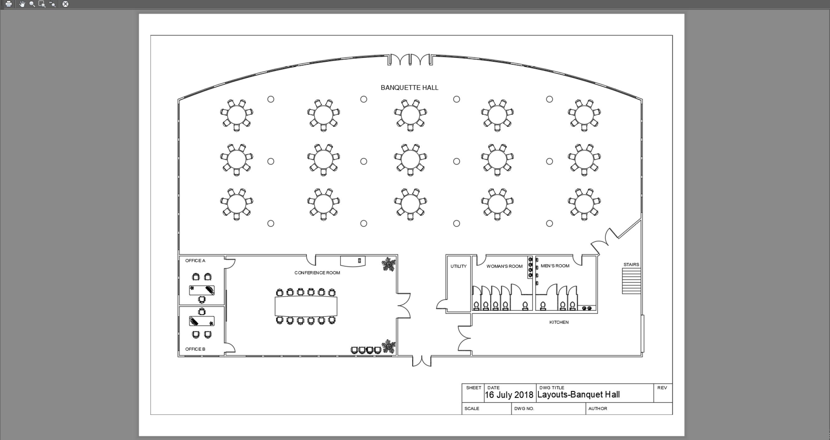
Now that you’ve selected the monochrome.ctb, you’ll want to apply this change to the layout defaults so all future plots from this layout will be correct. Click the Apply to Layout button to update the default Layout setup to use the monochrome.ctb Plot Style.
If you look in the Name field in the Printer/Plotter section of the Plot dialog box, you will see the Plotter is set to DWG To PDF.pc3. This means that Plotting the drawing will result in creating a .pdf file rather than a physical print, similar exporting files in other programs. This process is referred to as Plot to file. Click OK to plot the drawing. A save file dialog box will appear. Save the .pdf on your desktop. If you wish, double-click the file on your desktop to view the drawing in Adobe Acrobat, from which the file can be printed. As a.pdf file, the drawing can be sent to anyone with Adobe Acrobat DC or Acrobat Reader DC. Acrobat Reader DC is installed on most computers and devices and can be downloaded for free from the Adobe website, making.pdf files the most versatile option for sending and plotting your drawings, unless you are plotting directly to a physical plotter/printer.
Plotting from the Model Tab (Check Plotting)
Although it is usually best to plot from a Layout tab, you can also plot from the Model tab. This is referred to as a Check Plot because it’s generally only done so someone can check your work before the layouts are completed, and not for a finished plot you would use for actual building.
-
Switch to the Model tab. Press CTRL–P to bring up the Plot-Model dialog. Unlike the Layout tabs, the Model tab does not have saved plot settings. You’ll have to enter all the options, although you can save the options as a setup that you can use later.
- Select DWG To PDF.pc3 for the Plotter Name.
- For the Plot Style Table, select monochrome.ctb.
- For paper size, select ANSI A (11.5 X 8.50 Inches). Expand the What to plot: drop down menu. The options are Display, which will plot what’s visible on the screen, Extents, which will plot all of the objects in your drawing to the full extents of the sheet, Limits, which will plot all of the objects within the drawing limits, and Window, which will allow you to click and create a window around the objects you’d like to plot when you click OK.
- Choose Extents and check Center the plot under Plot Offset.
- Click the Add button in Page Setup area.
- Name the setup A-Size Landscape Extents. Now you can choose from the list without entering these options again.
- Choose Import from the Page Setup Name menu to import setups from other.dwg files.
-
Click the Preview button to open the Plot Preview dialog box so you can see how the plot will fit on the paper sheet. Click the Plot button
 in the upper right corner of the dialog box. If you click the Plot button in the Plot Preview dialog box, the file will plot directly without opening the Plot dialog box. Because you chose DWG to PDF as the plotter, you will be Plotting to File, so a save file dialog box will appear. Save the file to the desktop.
NOTE: You can scale a drawing when printing through the Model Tab by unchecking Fit to Paper and choosing a scale in the Plot Scale section, but your drawing might be too large to fit on the sheet of paper, and you will have difficulty positioning it on the sheet. It’s much easer to scale the drawing through viewports on Layout Tabs.
Settings for Layout tabs can be established by right-clicking on the tab and opening the Page Setup Manager. Layouts are created and saved with drawing template files (.dwt). You will learn how to configure Layout Tabs in templates in the Level 2 class.
Save and close the file.