Create a drawing in AutoCAD based on a mechanical template and explore various elements and settings saved to the template.
This exercise is excerpted from Noble Desktop’s past AutoCAD training materials and is compatible with Photoshop updates through 2020. To learn current skills in AutoCAD, check out AutoCAD Bootcamp and AutoCAD classes in NYC and live online.
Topics Covered in This AutoCAD Tutorial:
Using a Mechanical Template, Exploring Settings Saved to a Template
Exercise Preview
Exercise Overview
In this exercise, you will create a Drawing based on a Mechanical template and explore various elements and settings saved to the template.

Using a Mechanical Drawing Template
Press the QNew button
 in the Quick Access Toolbar or type QNEW Enter. Because you assigned the Mechanical-Inches.dwt template file to the QNew button in the last exercise, a new Drawing file base on Mechanical-Imperial.dwt will be created. If a.dwt file was not assigned to the QNew button, then the Select Template dialog box for the New command will appear when you press Qnew and you can navigate to the student folder and select Mechanical-Inches.dwt. You can refer to the previous exercise if you need to assign a Template to QNew.
Start the Save As command (CTRL–Shift–S or File > Save As). You will see that the file type is.dwg, not.dwt. Name the file Hub and save it to the student folder.
-
Start the Units command or select Units from the Format menu. The Drawing Units dialog box will appear, as shown below.
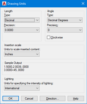
Note that the units are set to inches and the length type is set to Decimal. You will simply type distances in inches by their decimal value.
-
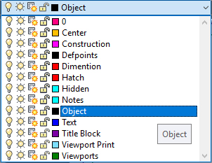
Expand Layer Control as shown. In mechanical drawings, layers are typically named according to the kind of line that is on that layer, as opposed to what kind of object is in an architectural drawing. You will see that the Current Layer is set to Objects because that is the Current Layer in the Mechanical-Inches.dwt file. New objects will be created on the Objects layer and will have the properties assigned to that layer. Keep the Current Layer set to Objects.
-
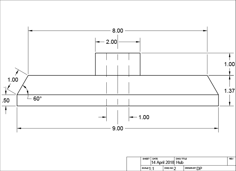
Now you will draw an object based on the dimensions given in the diagram below. Note the decimal units. The diagram is also annotated in a mechanical decimal dimensioning style.
Start the Rectangle command
 to make the base of the hub. Click anywhere to establish the start point of the rectangle, and then type 9,.5 for the X and Y values.
Make sure Polar Tracking is activated and set the incremental angle to 30˚.
-
Start the Line tool
 . Snap to the upper-left corner of the rectangle to establish the start point and draw the first line segment 1 inch at 60˚ as shown. Pull right and snap to the horizontal tracking line and type 8 for the distance. Snap to the endpoint on the upper-right corner of the rectangle to make the last line segment. Press Enter twice to end and restart the Line tool.
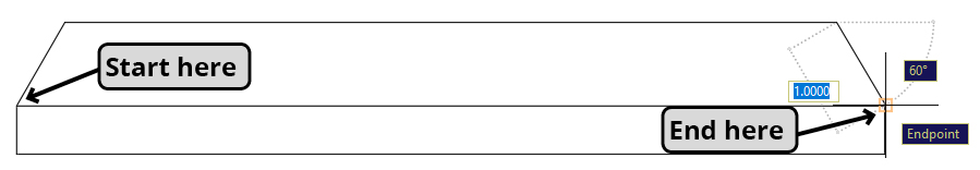
-
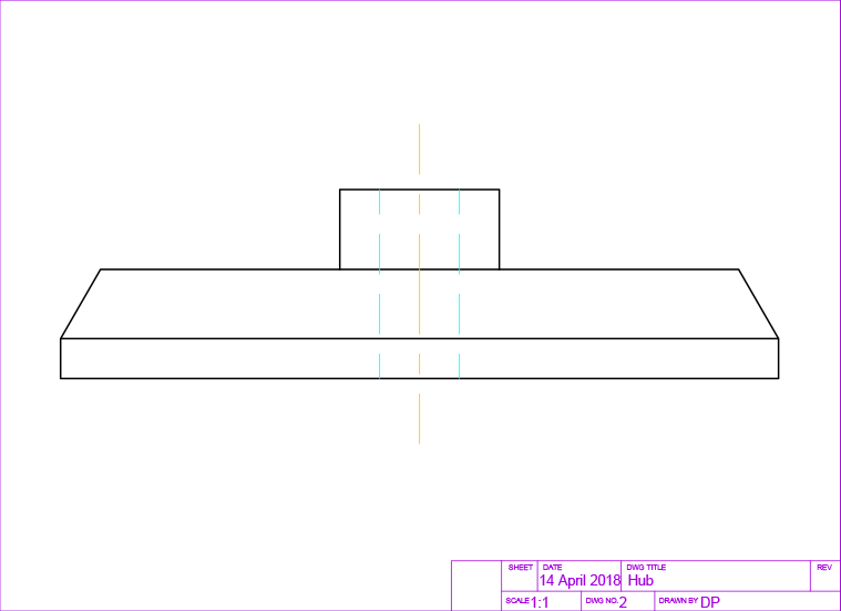
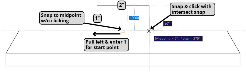
Without clicking, snap to the midpoint of the topmost line segment and pull to the left along the horizontal tracking line. Type 1 to start the new line segment 1 inch to the left of the midpoint. Pull upward along the vertical tracking line and type 1 and press Enter for the first line segment. Pull to the right along the horizontal Tracking line and enter 2 for the next line segment. Pull down on the 90˚ Tracking line and use the Intersect snap to snap the line to the top of the hub. Press Enter to end the line command.
-
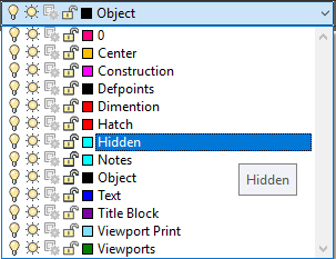
In the Layer Control, click the Hidden layer to make it the Current layer. Objects on the Hidden layer use the Hidden line type, indicating edges couldn’t be seen at the view angle of the drawing.
Press L Enter to start the Line Command
. Without clicking, snap to the midpoint of the topmost line segment and pull to the left along the horizontal tracking line and enter a distance of .5 to place the first point of the hidden line. Pull downward along the vertical tracking line and type 1 and press Enter for the first line segment. Pull down on the 90˚ Tracking line and use the Intersect snap to the snap the endpoint of the line to bottommost line of the hub.-
Press CO Enter to start the Copy command
 . Select the hidden line you just created. Click to any snap point on the line to establish the base point. Pull to the right along the horizontal tracking line and enter a distance of 1 to place a copy one inch to the right of the line.
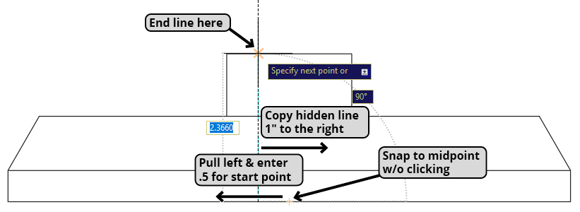
At a random spot on the side, make a vertical line 4 inches long.
-
Start the Move command
 and select the centerline you just made. For the base point, click the midpoint of the centerline. Snap to the midpoint of the second highest horizontal line as shown below.
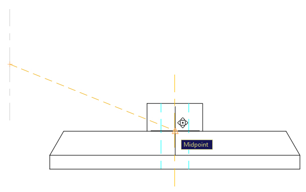
Close and save the file.