Discover how to use the Line Command to draw straight lines. You'll be introduced to how the Command Line works and how to use keystrokes to specify the distance and angle for each line to draw the complex shapes.
This exercise is excerpted from Noble Desktop’s past AutoCAD training materials and is compatible with Photoshop updates through 2020. To learn current skills in AutoCAD, check out AutoCAD Bootcamp and AutoCAD classes in NYC and live online.
Topics Covered in This AutoCAD Tutorial:
Intro to the Line Command
Exercise Preview
Exercise Overview
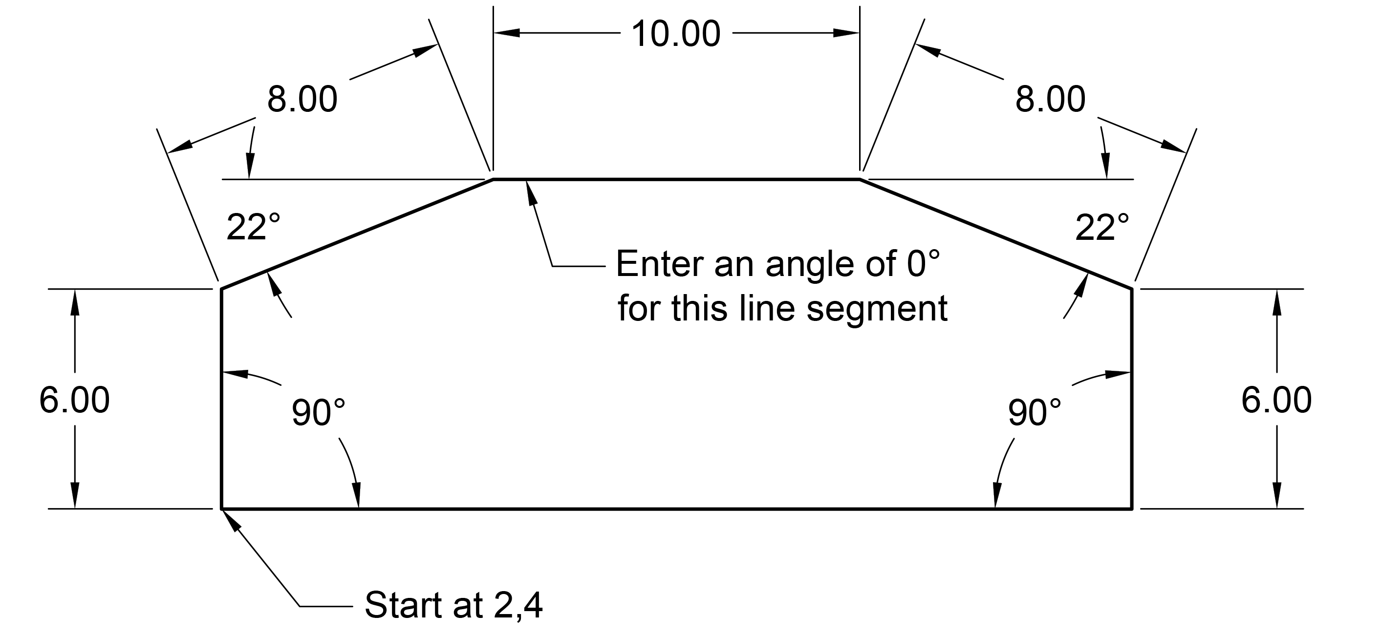
In this exercise, you’ll learn how to use the Line Command to draw straight lines. You’ll be introduced to how the Command Line works and how to use keystrokes to specify the distance and angle for each line to draw the shape shown above.

Getting Started
- If AutoCAD isn’t already open, launch it now.
- You should see the Start tab.
-
Click on the large Start Drawing button.
A new Drawing1 tab will open. Drawing files use a.dwg file format and are based on a Drawing Template file (.dwt). For now we’ll use the default template file, but you’ll see how to use customized templates in a later exercise.
Using the Line Command
-
In the lower right corner, notice the Status Bar.
This contains buttons that can be used to turn some useful features on or off. When a button is turned on, it’s highlighted in blue.
- For now, we want to make sure both Polar Tracking
 and ORTHOMODE
  are disabled. If either option is blue, click it to switch it off. You’ll learn how these work in the next exercise.
 - Let’s start drawing a line. In the Ribbon panel at the top of the screen, click on the first Line tool
 .
. -
At the bottom of the screen, notice that choosing the tool has activated the Command Line panel.
The Command Line
When entering a command with the mouse or keyboard, it appears in the Command Line. You’ll see the command you are in, the stage of the command, and the options that are available. Paying close attention to the Command Line will make you a more effective user.
-
As you’ll see with most AutoCAD drawing tools, the first step when a command is entered is to specify the start point. While we could click with the mouse to specify a coordinate, let’s be more specific and type it in:
To specify the starting point for our shape, press the 2 key, comma (, ), then 4 key again so that you end up with 2,4 in the command line:

Press the Enter key to apply the start point coordinates.
-
Using the mouse, move the cursor upwards to indicate the direction of the next point.
NOTE: You need to use the mouse to point in the general direction you want the line segment to go before entering the distance and angle values.
-
To enter the desired distance amount, type 6, then press Tab to switch to the angle input field.
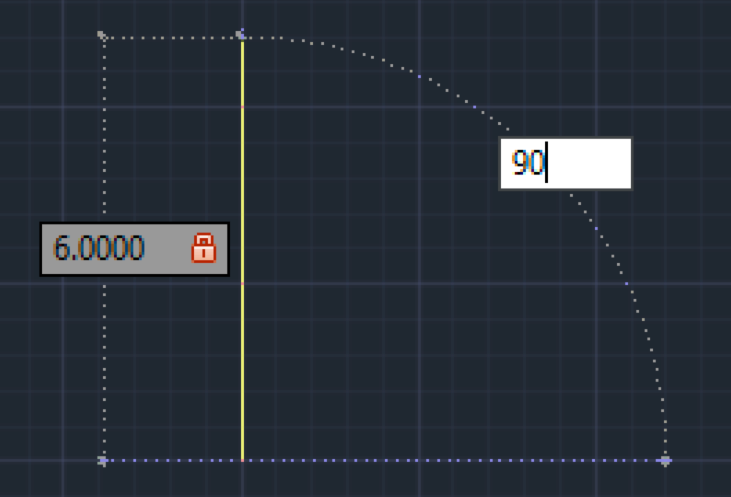
We want a 90° angle for this line so type 90 and press Enter. You have just completed your first line segment!
-
For the next line segment (the angeled top-left corner):
- Move the cursor towards the right (to indicate direction).
- Type in a distance of 8 units.
- Press Tab.
- Enter an angle of 22°.
- Press Enter to finish drawing the line segment.
-
For the next line segment (the horizontal top):
- Move the cursor towards the right.
- Type in a distance of 10 units.
- Press Tab.
- Enter an angle of 0°.
- Press Enter to finish drawing the line segment.
-
For the next line segment (the angeled top-right corner):
- Move the cursor towards the right.
- Type in a distance of 8 units.
- Press Tab.
- Enter an angle of 22°.
- Press Enter.
-
For the next line segment (the vertical right side):
- Move the cursor towards down.
- Type in a distance of 6 units.
- Press Tab.
- Enter an angle of 90°.
- Press Enter.
- We can use the Close option to both close the shape and end the command. To draw the bottom horizontal line segment, in the Command Line click Close.
- Congratulations, you’ve just drawn your first shape! Save the file by going to File > Save As.
- Navigate into Class Files > AutoCAD Class.
Name the file my first line drawing.dwg and click Save.