Master the nuances of using Dimensioning Tools in AutoCAD with this comprehensive tutorial, including hands-on exercises and detailed explanations of tool aliases, their applications, and mechanical dimension tools.
This exercise is excerpted from Noble Desktop’s past AutoCAD training materials and is compatible with Photoshop updates through 2020. To learn current skills in AutoCAD, check out AutoCAD Bootcamp and AutoCAD classes in NYC and live online.
Topics Covered in This AutoCAD Tutorial:
Dimensioning Tools, Editing Dimensions
Exercise Preview
Exercise Overview
In this exercise, you will learn how to use the Dimensioning Tools to add dimensions to your drawings so that measurements can be displayed. Dimensioning tools can be found in the Dimension Toolbar, the Annotation Panel on the Home tab of the Ribbon, or in the Dimension Pane l in the Annotate tab.

Dimensioning Tools
Most dimensioning tools follow a formula for their aliases to make them easier to remember. The formula is a D, plus the first two letters of the tool. For example, the Linear Dimension tool, or DIMLINEAR, is DLI. The Aligned Dimension tool, or DIMALIGNED, is DAL. The Angular Dimension tool, or DIMANGULAR, is DAN, and so on. Below is a list of dimensioning tools covered in this exercise that follow this formula.
- DLI: Linear Dimension Tool (DIMLINEAR)
- DAL: Aligned Dimension Tool (DIMALIGNED)
- DAR: Arc Length Dimension Tool (DIMARC)
- DRA: Radius Dimension Tool (DIMRADIUS)
- DJO: Jogged Dimension Tool (DIMJOGGED)
- DDI: Diameter Dimension Tool (DIMDIAMETER)
- DAN: Angular Dimension Tool (DIMANGULAR)
- DBA: Baseline Dimension Tool (DIMBASELINE)
- DCO: Continue Dimension Tool (DIMCONTINUE)
Mechanical Dimension Tools
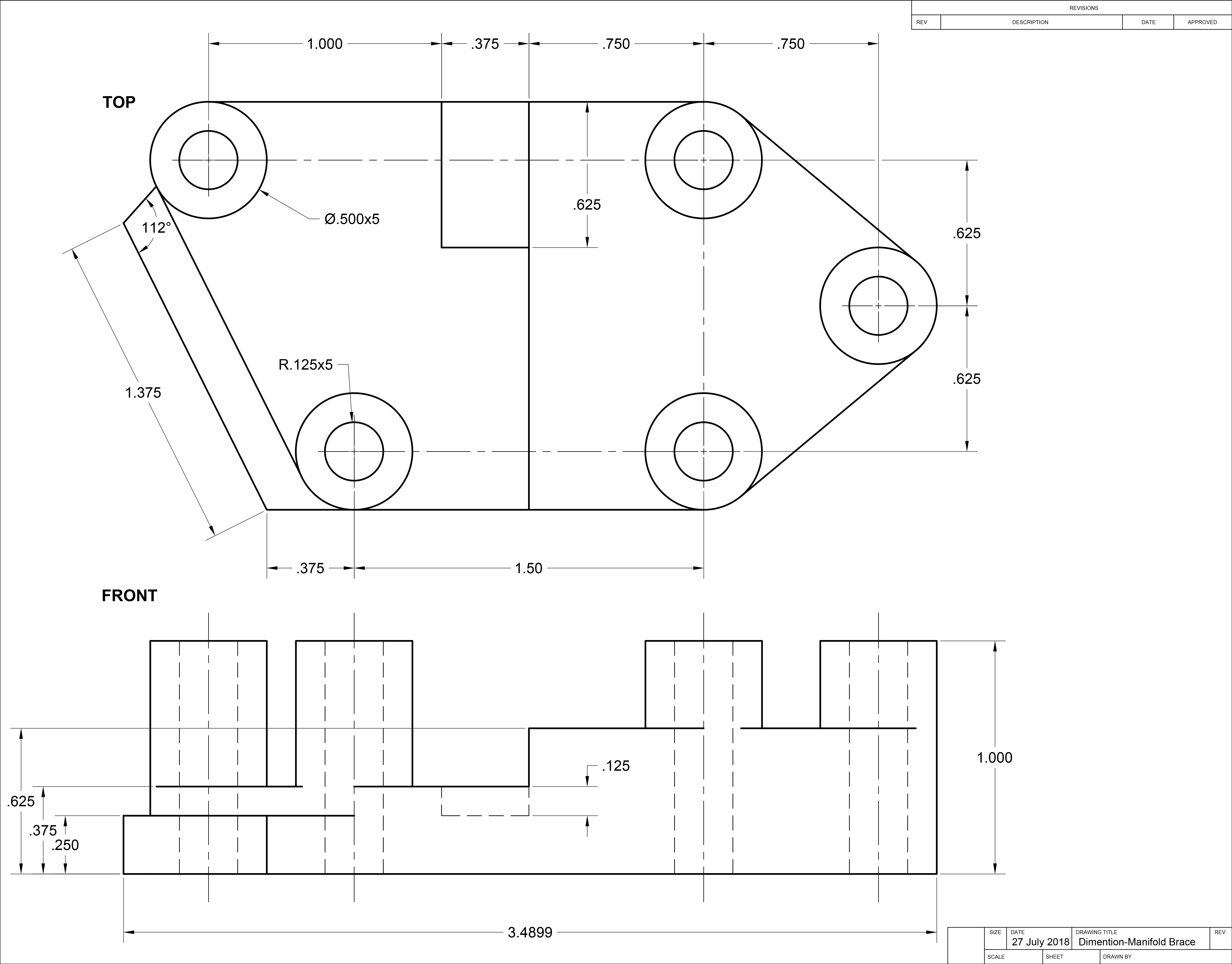
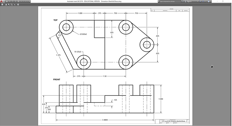
Open the file Dimensions-Manifold Brace.dwg.
Switch to the C-Sized Layout and to Model Space. Change the current layer to Centerlines.
-
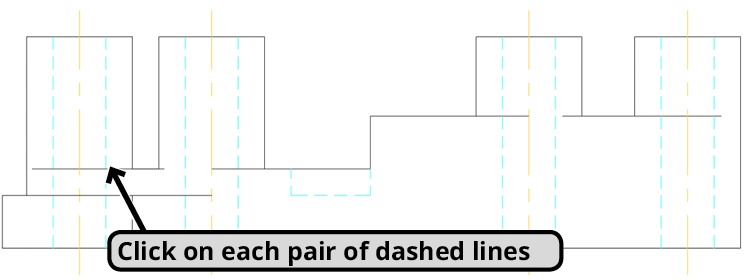
In the front view at the bottom of the viewport, there are dashed lines that represent the hidden edges of circular holes. In this situation, you must make centerlines to indicate the holes are circular and denote where the center points will align in another view. You can easily create centerlines with the Centerline tool. You can start the tool by pressing the Centerline button or typing Centerline ENTER.
Start the Centerline tool. Click on each of the first two dashed hidden lines from the right. A centerline will appear between them. Restart the tool and click on the rest of the hidden lines to create centerlines between each pair.
-
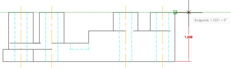
Change to Paper Space. Type DLI ENTER to start the Linear Dimensioning tool. Even though you are in Paper Space, the Dimensioning Tools will snap to the model and make measurements of the objects in the model.
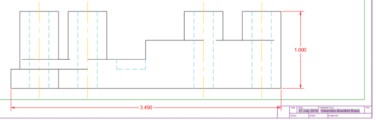
On the front view of the object at the bottom of the viewport, snap and click on both corners of the right side of the object as shown below. A linear dimension will be created in the Paper Space. Pull to the right and type 1 ENTER so that the dimension line will be 1 inch from the object in the Paper Space.
-
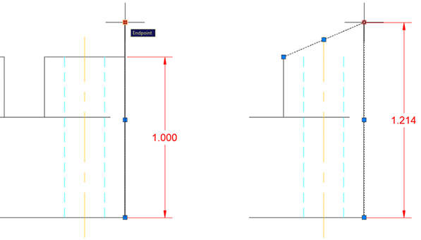
Change to Model Space. Dimensions are associative, meaning they are associated with the objects they are dimensioning and will adapt if the measurements of the objects change.
Select the line segment at the right edge of the object you just dimensioned. Click the top grip and extend the line upward. Select the line at the top edge and click the right grip and connect it to the top of the line you just extended. As the lines are moved and the shape of the object is changed, the linear dimension will follow and the displayed measurement will update. Undo the changes.
-
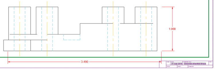
Use the Linear Dimension tool to dimension the bottom edge of the object as shown below. Remember to enter a distance of 1 when pulling out the dimension lines. The dimension lines will intersect with the title block. You will solve this problem in the next step.
-
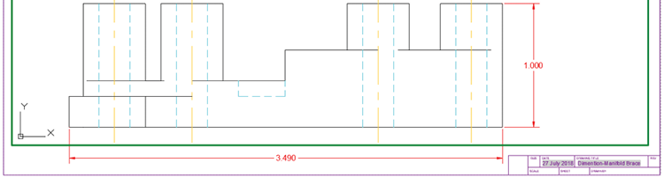
You must reposition the model so that the lower dimension will not overlap the title block. Switch to Model Space and unlock the viewport. Use the mouse wheel to Pan the model to the left until the right edge of the model is slightly to the left of the title block as shown below. Don’t move it too far left, you will need some space on the left side of the object later. The dimensions in the Paper Space will remain stationary. You will fix this in the next step.
-
Type DIMREGEN and press ENTER. The DIMREGEN command will reposition the dimensions so that they match the new position of the model. You may need to manually reposition some of the dimensions with grips when you use the DIMREGEN command. Lock the viewport and switch back to Paper Space.
-
Use the Linear Dimension on the leftmost edge of the front view of the object as shown below, once again with the dimension lines 1 inch from the object (you will use this for Baseline Dimensioning later).
-
The Linear Dimension tool is orthographic, meaning it will only make vertical or horizontal dimensions. You will use the Aligned Dimension tool to dimension the lengths of angled edges.
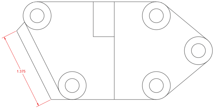
Type DAL ENTER to start the Aligned Dimension tool. Snap to each endpoint of the angled edge of the top view, pull outward from the object, and type 1 ENTER to make the dimension line one inch from the object as shown below.
-
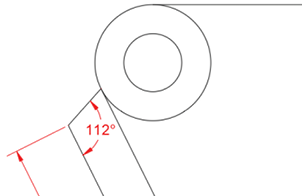
Type DAN ENTER to start the Angular Dimension tool. With the Angular Dimension tool, you will click on two line segments, rather than clicking on object snap points to determine the angle between the lines. Click on the angled line you just dimensioned with the Aligned Dimension tool, and then click on the other angled line which is connected to the top of the first line as shown below. Pull to the right until the dimension lines fit in the available space as shown below. In this case, there is not enough room to enter a dimension line offset distance of 1 inch.
-
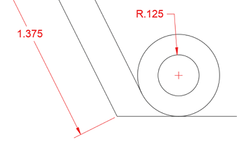
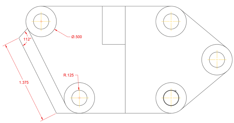
Type DRA ENTER to start the Radius Dimension tool. Click on the inner circle from the pair of concentric circles in the lower left corner and type 1 ENTER so that the dimension will be one inch away and automatically positioned as shown below. A small center mark will appear in the circle.
-
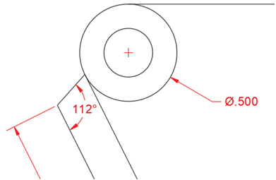
Type DDI ENTER to start the Diameter Dimension tool. Click on the outer circle from the pair of concentric circles in the upper left corner and type 1 ENTER so that the dimension will be one inch away and automatically positioned as shown below. A small center mark will appear in the circle.
-
Now you will place center marks in all the circles that will allow you to create center lines that will show the center points are aligned with the Centermark tool.
Change the Current Layer to Centerline.
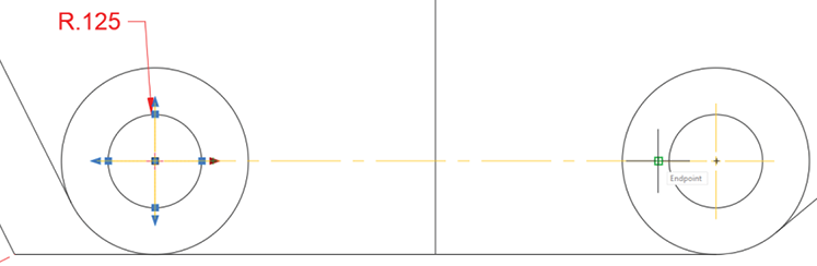
Type CENTERMARK ENTER or press the Centermark tool button in the Centerlines Panel on the Annotate Ribbon tab to start the Centermark Tool.
Click on all 5 of the inner circles of the top view of the object to add center marks to each circle. Press Enter or Esc to exit the Centermark tool.
-
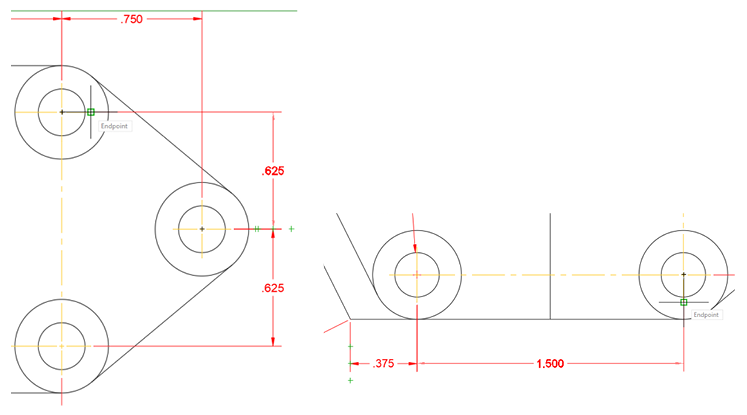
Select the Centermark in the lower left corner. Click on the right grip of the Centermark and move it to the right until it snaps to the left Endpoint of the Centermark on the right as shown below. A Centerline will be formed indicating that the center points of the two circles are horizontally aligned.
-
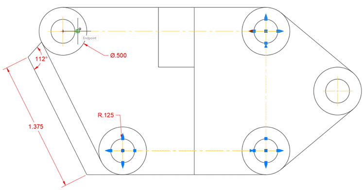
Repeat the process from the last step to connect the bottom right, top right, and top left Centermarks as shown below.
-
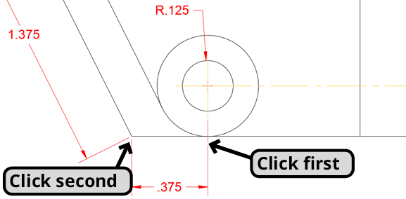
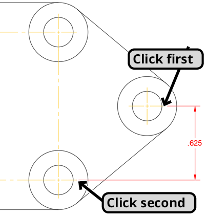
Change the Current Layer to Dimensions. Type DLI to start the Linear Dimension tool. Make Linear dimensions between the bottom endpoint of the center mark at the lower left and the lower left endpoint of the object. Click the Centermark first so that when you enter a dimension line offset of 1 inch, it will be from the lower corner of the object and not the Centermark as shown below.
-
Restart the Linear Dimension tool. Click on the right endpoint of the lower right Centermark, then click the right endpoint of the rightmost Centermark, pull to the right and enter a distance of 1. Stay in the Linear Dimension Command.
With the Linear Dimension tool, click on the top endpoint of the upper left Centermark and the top endpoint of the next vertical edge to the left as shown below. Once again, enter a dimension line offset distance of 1.
-
Now you will make side by side dimensions adjacent to the Linear dimensions you just created by using the Continue Dimension tool.
Type DCO Enter to start the Continue Dimension tool. By default, the Continue Dimension tool will continue from the last dimension you created, in this case the top left Linear Dimension you just created. If prompted to select a dimension, click on the last one you made. Click on the next vertical edge to the right, and then the next two Centermarks as shown below. The Continue Dimension tool will still be active. In the command line you will see the
<Select>option. Press Enter to choose the<Select>option for the next step.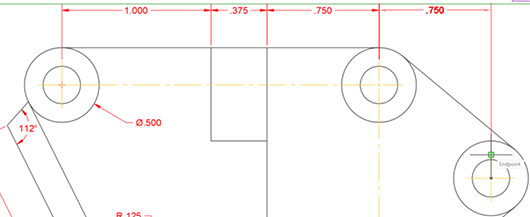
-
Click the top extension line of the Linear Dimension on the right side between the bottom and middle Centermarks as shown below. Press Enter to choose the
<Select>option again.Click on the right extension line of the horizontal Linear Dimension on the bottom left of the object and continue the dimension to the next Centermark to the right. Press Enter twice, once to choose the select option and then to end the command.
-
Another way to create side by side dimensions is with the Baseline Dimension tool. Unlike Continue Dimension, Baseline measures all dimensions from a single baseline instead of point to point the way that Continue does.
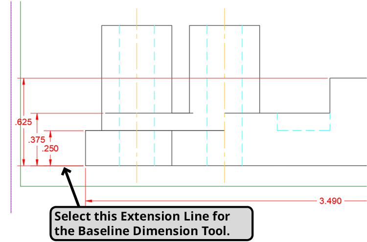
Type DBA ENTER to start the Baseline Dimension tool. Just like the Continue tool, the Baseline Dimension Tool will use the last dimension you made as the baseline by default. The Baseline tool also has a
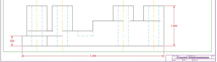
<Select>option in the command line. Press Enter to choose the<Select>option.In the front view, click on the bottom extension line of the Linear Dimension in the lower left measuring .250. It’s important to click on the correct extension line when using the Baseline Dimension tool because that specific extension line will be the baseline for the side by side dimensions created by the tool. Pull upward and click on the next 2 vertical edges as shown below. Press ENTER twice or Esc to end the Baseline Dimension Tool.
-
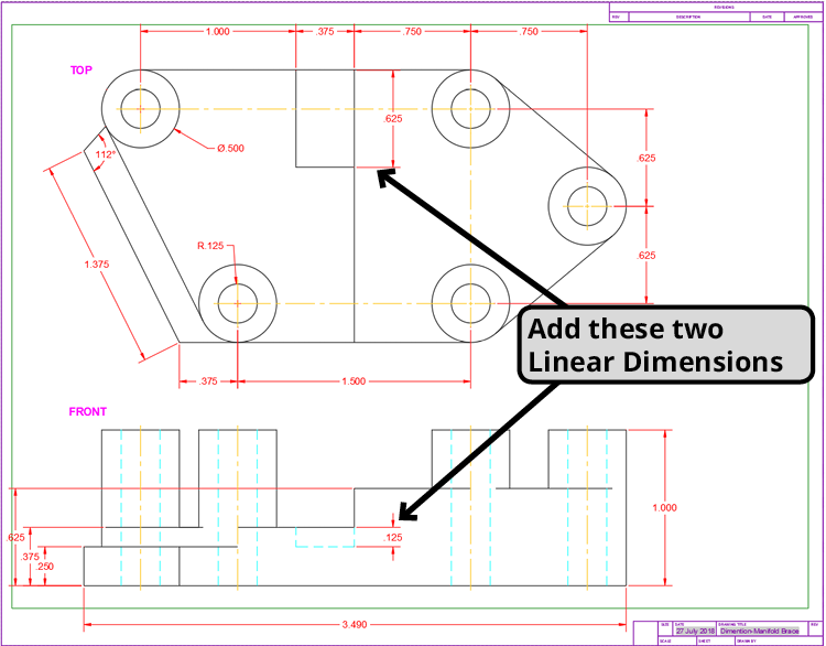
Finish dimensioning the object by creating the two additional Linear Dimensions shown below. Remember to enter 1 for the dimension line offset distance.
Editing Dimensions
-
Just like text, you can change the properties of a dimension by assigning a different Style. A Style is a saved set of options that can be assigned to objects. You can change the style in the expanded Annotation Panel or Annotate tab in the Ribbon, the Style or Dimensio n Toolbar, or the Properties Pallet. You can also select the dimensions and change the Style in the right-click menu.
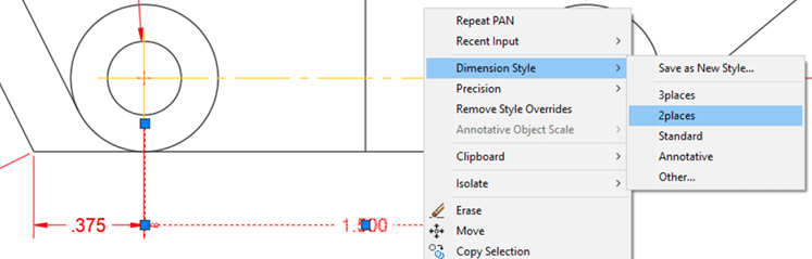
Select the Linear Dimension below the top view that measures 1.500 and right-click. From the right-click menu select the Style sub menu, and then select 2 Places. The dimension will change from 3 decimal places to 2, as defined by the 2 Places Style. The measurement will now be displayed as 1.50.
Select the Linear Dimension at the bottom of the front view that measures 3.490. These dimensions you’ve made use the 3 places dimension style, so the precision is set to 3 decimal places (0,000). With the dimension selected, right-click, and from the menu select the precision sub menu, and then 4 decimal places (0.,000). The dimension now measures 3.4899.
-
Select the vertical Linear Dimension near the center of the top view that measures 6.25. The dimension text is a bit too close to the centerline connecting the circles. Click on the grip on the text and move it downward along the dimension line as shown below.
-
There are 5 pairs of circle in the top view, which you only dimensioned once. You will need to indicate that the dimensions are repeated for the other circles. You can edit or add to the dimension text by double-clicking on it.
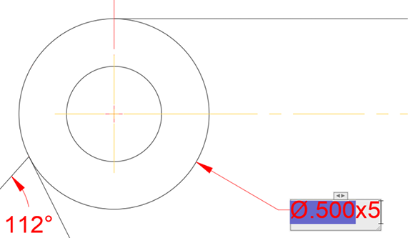
Select the Diameter Dimension in the upper left corner of the top view. Double-click on the text. You will enter text editing mode and the Text Editor Ribbon tab will appear. The dimension measurement will have a blue background and there will be a blinking cursor. Use the right arrow key to move the cursor to the right of the measurement. Type x5, and make sure you don’t overwrite the measurement text. Press Esc to exit the Text Editor and then press Enter to accept the changes. Repeat the process for the Radius Dimension at the bottom left corner.
-
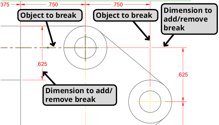
In the upper right corner of the top view, the Extension Lines and the horizontal and vertical Linear Dimensions that measure 7.50 and 8.50 overlap each other. This can cause confusion in the final plot because overlapping dimensioning lines can be mistaken for actual objects. You can use the Dimension Break tool to clarify what belongs to the dimension and what belongs to the objects in the drawing.
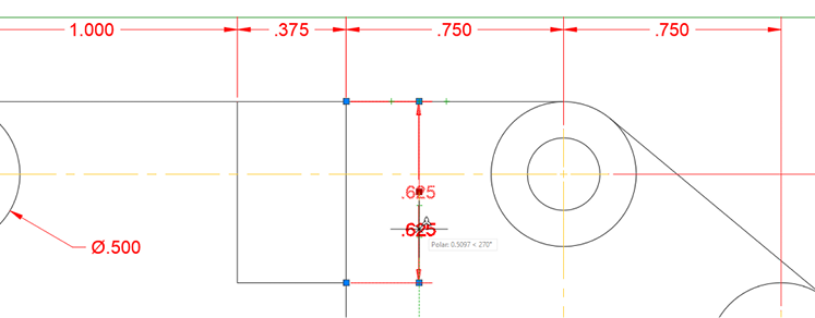
Type DIMBREAK ENTER or press the button to start the Dimension Break tool. For the dimension to add/remove break, select the upper extension line of the dimension measuring .625. For object to break press Enter to select the
<Auto>option. You can also manually select objects if you don’t want every intersecting object to make a break in the dimension.Repeat the process for vertical Lineal Dimension in the upper middle area of the top view measuring .625, and select the centerline connection in the top circles for the object to break as shown below.
-
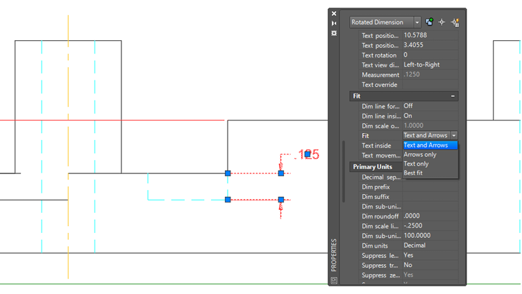
Now you will edit a dimension using the Properties Pallet. Most of the options available for editing dimensions can be found in the Properties Pallet.
In the front view, select the Linear Dimension measuring .125 that dimensions the dashed hidden edge cut out in the middle of the object. Open the Properties Panel (CTRL–1). Scroll down in the Properties Panel to the Fit options. Click on the Fit drop down menu and select Text and Arrows. The text will shift from inside the extension lines to outside.
-
Start the Preview command. Zoom and Pan to view different parts of the drawing. Note how the difference in lineweight as defined by the layers makes it clear which are dimension lines and which are part of the objects. Close the Plot Preview dialog.
Close and save the file.