All drawings in AutoCAD have an absolute XY plane with an origin at 0,0 on a Cartesian XY grid. Learn about the Cartesian XY Grid and its importance in AutoCAD.
This exercise is excerpted from Noble Desktop’s past AutoCAD training materials and is compatible with Photoshop updates through 2020. To learn current skills in AutoCAD, check out AutoCAD Bootcamp and AutoCAD classes in NYC and live online.
Topics Covered in This AutoCAD Tutorial:
Entering Coordinates, Angles, & the UCS
Exercise Preview
Coordinates
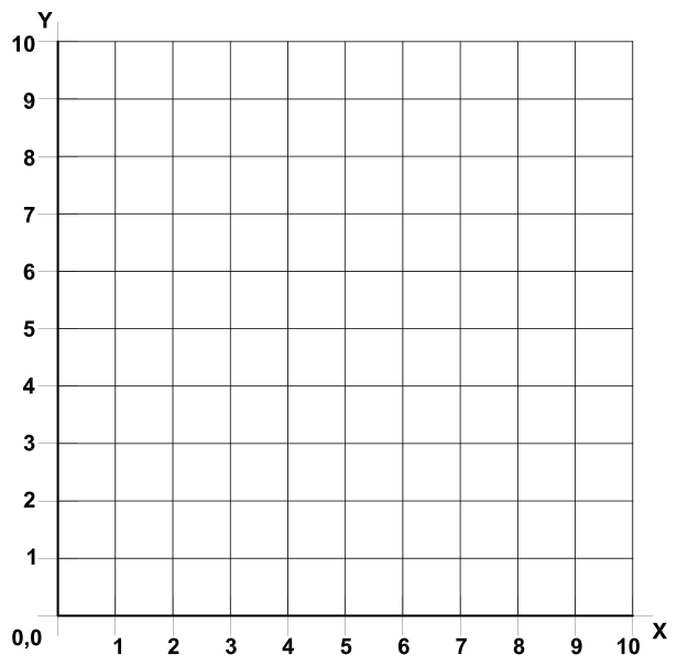
All drawings in AutoCAD have an absolute XY plane with an origin at 0,0 on a Cartesian XY grid. Cartesian is a mathematical term referring to the XYZ axis coordinate grid system. In this book only 2-dimensional drafting will be addressed, so the Z-axis will not be used. However, the Z-axis is utilized in the full version of AutoCAD for 3D modeling. 3D modeling tools are not included in AutoCAD LT.

All objects and points in every AutoCAD drawing are located at a specific location on the XY grid. When 2D drafting in AutoCAD, you are always drawing in a top-down view in which the X-axis is horizontal, and the Y-axis is vertical. Coordinates in AutoCAD are entered X, Y. For example, if you are specifying the first point of a drawing tool at 3 on the X-axis and 5 on the Y-axis, you would type 3,5.
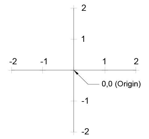
Positive X values are to the right of the Origin Point, and negative X values are to the left. Positive values of Y are above the Origin Point, and the negative Y values are below. If a coordinate is located 3 units to the left and 2 units below the Origin Point, you would enter a coordinate value of –3, –2.
Coordinates in AutoCAD can be set to Absolute, meaning all coordinates entered are relative to the Origin Point, or Relative, meaning some coordinates are relative to other objects on the grid when using certain tools. The default setting is Relative. For example, when using the Rectangle tool, you enter the width and height relative to the start point if coordinates are set to relative. If coordinates are set to absolute, after entering the start point of a rectangle you must enter the XY coordinate of the opposite corner rather than entering width and height. The coordinate setting can be found by Right–clicking on the Dynamic Input button ![]() on the Status Bar and selecting Dynamic Input Settings and then pressing the Settings button under pointer input. If you turn off the Dynamic Input, AutoCAD will revert to Absolute coordinates. For this reason, most users should keep the Dynamic Input on because Relative coordinates are generally more useful.
on the Status Bar and selecting Dynamic Input Settings and then pressing the Settings button under pointer input. If you turn off the Dynamic Input, AutoCAD will revert to Absolute coordinates. For this reason, most users should keep the Dynamic Input on because Relative coordinates are generally more useful.
Angles
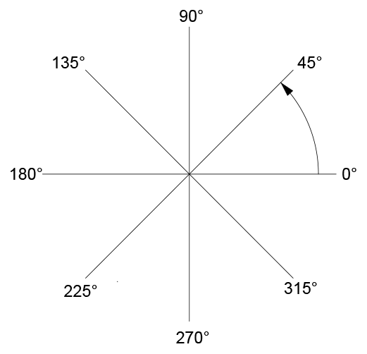
Angles in AutoCAD are counter clockwise from the 0° horizon line. Just as with coordinates, angles can be relative, measured from a polar angle or previous line segment, or absolute, measured from the 0° horizon depending on the circumstance.
Forced Absolute or Relative Values Using # or @
There may be times when you’ll need to enter absolute coordinates or angles. If you type # (Shift 3) before a coordinate or angle as it’s entered, it will be absolute relative to the Origin Point or the 0˚ horizon. Typing @ (Shift 2) will force values to be relative, which is unnecessary in most circumstances because Relative is the default.
UCS Icon
UCS stands for User Coordinate System. The UCS allows the user to reposition the Origin Point and XY and Z axes. In 2D, the UCS Icon displays the orientation of the X and Y axes. The UCS Icon ![]() will either be located at the bottom-left corner of the screen or the Origin Point or turned off entirely depending on settings. In the View Menu, you can select Display > UCS. If the On option is highlighted, the UCS Icon will be visible, and if the Origin option is highlighted, the UCS Icon will be set to the Origin Point. By default, you can select the UCS Icon and move it or snap it to other objects to change the Origin Point. However, when you move the USC Icon, you are deviating from the default absolute XY plane. The absolute default XY plane is referred to as the World Coordinate System or WCS. You might do this to enter coordinates relative to a specific point other than the Origin, but deviating from the WCS can be problematic if done accidentally, or the UCS is not reset to the WCS default. If you’ve moved the UCS Icon or shifted the UCS by other methods, you can reset to the WCS entering the UCS Command and select the World option, or click on the UCS menu below the View Cube and select WCS. To avoid accidentally moving the UCS Icon, you can use UCSICON Command to make the UCS Icon unselectable. Choose the Selectable option and set it to off. The UCSICON Command also has the same option of On and Origin as found in the View > Display > UCS Icon menu.
will either be located at the bottom-left corner of the screen or the Origin Point or turned off entirely depending on settings. In the View Menu, you can select Display > UCS. If the On option is highlighted, the UCS Icon will be visible, and if the Origin option is highlighted, the UCS Icon will be set to the Origin Point. By default, you can select the UCS Icon and move it or snap it to other objects to change the Origin Point. However, when you move the USC Icon, you are deviating from the default absolute XY plane. The absolute default XY plane is referred to as the World Coordinate System or WCS. You might do this to enter coordinates relative to a specific point other than the Origin, but deviating from the WCS can be problematic if done accidentally, or the UCS is not reset to the WCS default. If you’ve moved the UCS Icon or shifted the UCS by other methods, you can reset to the WCS entering the UCS Command and select the World option, or click on the UCS menu below the View Cube and select WCS. To avoid accidentally moving the UCS Icon, you can use UCSICON Command to make the UCS Icon unselectable. Choose the Selectable option and set it to off. The UCSICON Command also has the same option of On and Origin as found in the View > Display > UCS Icon menu.
![]()